
|
Rigidizable Inflatable Starshade Joseph Subasic, Anjolie Tuazon, Howard Community College Mentored by: Brendan Diamond, Ph.D. |
Abstract
An orbiting starshade, resembling a giant flower petal, offers a solution for directly imaging exoplanets by blocking starlight. This study aims to design a simpler, radically lighter, inflatable starshade to reduce mission costs. Through computational modeling and a 1:100 scale physical model, we explore inflatable variants, achieving significant mass reduction without sacrificing performance. Results demonstrate the potential for substantial cost savings throughout mission lifecycles. The inflatable starshade’s adaptability and scalability offer versatility for various mission architectures. Our research not only enhances exoplanet imaging capabilities but also showcases the broader impact of lightweight inflatable structures in space exploration. The total design mass between 438kg and 546kg, halves the mission’s 1000kg maximum. The development of a lightweight inflatable starshade represents a significant advancement in cost-effective exoplanet imaging, promising new frontiers in our understanding of distant worlds.
Introduction
The Starshade
The starshade is a proposed technology designed to enable astronomers and cosmologists to directly image planets around other stars (exoplanets) to search these planets for signs of life [1]. Originally conceptualized by Lyman Spitzer in 1962 [2], it was further developed and engineered by astronomers Webster Cash and Sarah Seager, yet no design has ever been launched into space [3]. A launched and deployed into orbit starshade would be positioned in-line with a space or ground-based telescope. The specific shape of the starshade is designed to control diffraction by projecting a shadow
optimized to block out light from an exoplanet’s host star while allowing reflected light from the exoplanet to reach a telescope (Figure 1). This improved clarity allows observers to obtain information on characteristics such as the exoplanet’s size, spectra, and orbitfrom the exoplanet’s light, as the exoplanet’s light is not interfered with while the starshade is up due to its angular separation of the host star [4].
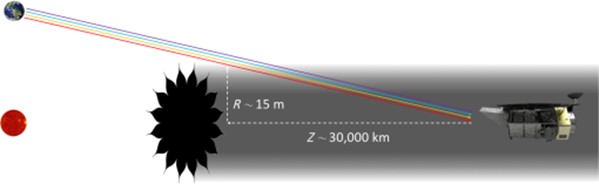
Figure 1: A starshade blocking out the light from the host star in order for the telescope to image the exoplanet [5]
Without the starshade, more complex optics would be needed to be able to directly image the exoplanet without blocking the starlight, making the starshade a potentially simpler and more cost-effective approach. However, there are still outstanding challenges with the development of the final design of the starshade. There has not yet been a peer-reviewed design that conforms to the payload restrictions of current space launch vehicles.
Starshade Design Challenges
A NASA mission set to launch in the 2030s, the Habitable Exoplanet Observatory (HabEx), seeks to directly image Earth-like exoplanets for signs of habitability [6]. HabEx proponents initiated a design challenge to the public for a starshade that can stow away for launch in the Falcon 9 rocket with a mass at most of 1,000 kg, as the cost of the mission is related proportionally to the mass of the starshade [7].
The overall structural design of the starshade requires specific dimensions and a specific shape to optimally reduce sunlight scatter towards the telescope. The starshade must have a total diameter of 100 meters, accommodating a central disk with a diameter of 50 meters and surrounded by at least 24 petals that are 25 meters long. The petals must have edges that are “thinner than paper” with an edge shape tolerance of five millimeters and in-plane deflection of five centimeters. In the center of the starshade resides a two-meter-in-diameter empty cylinder that will house the spacecraft bus and propellant tanks. While the starshade is stowed away during launch, the compressed dimensions need to be no more than 14 meters long and 4.5 meters in diameter to fit in the Falcon 9 rocket compartment.
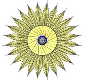
Figure 2: Example structural design of a starshade with foldable supports causing high mass [8]
Inflatable Structures
Inflatable structures have been commonly used in space as satellites, as these simple structures are extremely lightweight and can withstand variable forces when rigid, such as NASA’s Project Echo. Introduced as the first inflatable in space, Project Echo consisted of two large experimental balloons that functioned as communications satellites that orbited around Earth [9]. The balloons were comprised almost entirely of a specially designed aluminum-coated mylar to increase the inflatable’s tolerance to micrometeoroid strikes and tearing. The first design Echo 1, launched in 1960, had a diameter of 30 meters and stayed in orbit for nearly eight years [9]. The second design, Echo 2, was launched in 1964, had a diameter of 40 meters and stayed in orbit for five years. Echo 2 was rigidized by internal pressure from a sublimating compound, able to maintain shape for long periods without the need for frequent reinflation and a higher tolerance to micrometeoroid strikes [10].
To combat the challenges with mass and compactness, we propose a rigidizable starshade design with inspiration taken from these Project Echo satellites. Due to their rigidity and high tolerance to micrometeoroid strikes, the design of these inflatable satellites serves as the perfect precedent for an inflatable starshade. However, rather than taking inspiration from Project Echo’s spherical shape, the starshade will have a rather flat shape made of the material inspired by the special mylar used in Project Echo.
Rigidizable Starshade Design & Analysis
Our Starshade Design
We propose a rigidizable inflatable starshade design to address the challenges regarding heavy mass and load packaging into the Falcon 9 rocket. This rigidizable inflatable starshade design takes the same shape and size as the proposed JPL design [1], however, the starshade is completely inflatable with no metals, struts, beams, etc. Doing so allows us to reduce the weight by an extremely large amount and allows for easy packaging with plenty of space inside the Falcon 9 rocket by folding the starshade prior to launch and inflating while on orbit. However, to meet the optical requirements the starshade must be extremely thin with “paper-thin” edges but must also be able to withstand the force induced by the thrusters that move the starshade throughout space. Inflatables are generally not rigid bodies when extremely thin, but cylindrical gas channels throughout the shape of the starshade will allow the inflatable starshade to be rigidizable. In Figure 3, we lay out the outlines for the gas channels. No structural tubing will be used for the gas channels but rather the inflatable material will be bonded together in all areas except for the path of the gas. This results in the entire starshade structure, often called “the mask”, being made with only one material: special mylar except for metallic optical tips on each petal.
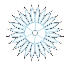
Figure 3: Rigidizable Inflatable starshade gas channel layout (light blue)
The special mylar chosen for our starshade was inspired by the special mylar used for the Project Echo satellites. Mylar is a plastic film known for its impermeability, having high tensile strength, and resistance to extreme temperatures, while also being extremely lightweight and ultra-thin, making it a popular choice for the mask of inflatables. The special mylar used in Echo 2 is a duPont 35-gauge type C, that is 0.35 mil ± 10 percent thick, sandwiched between two 1080 Aluminum films[10]. The 1080 Aluminum film brings not only extra protection to the inflatable, but also has a low yield point, requiring less internal pressure to rigidize. The three films were adhered together by the GT 301 manufactured by G.T. Schjeldahl Co. [10].
Hyper-Gaussian Apodization Function Matching
The starshade was designed to take a hyper-Gaussian shape as it prevents various wavelengths of light, including blue light, from passing through [12], enabling the starshade to be built with integrated starlight suppression. Since the entirety of our inflatable starshade mask is designed to be built with mylar films bonded together, the calculation of the structural mass heavily relies on the starshade’s total surface area. Without the original data, we are unable to produce the exact same apodization function used to create the starshade’s hyper-Gaussian shape, which is needed to calculate the total surface area. Therefore, creating a function that matches the original hyper-Gaussian shape of the starshade will enable us to determine the total mass, as well as aid in the creation of a 1:100 scale model.
The hyper-Gaussian shape of the starshade was noticeably like the shape of a sinusoidal polar function with an even number of petals. Therefore, the given radius of the central disk and the given length of the entire starshade were set as guidelines for creating a similar function. We developed such function by graphing a basic polar function centered about the origin on Desmos, then modified the function until we came to a function that closely resembled the original hyper-Gaussian shape of the starshade with matching dimensions for 24 petals [11]. That is,
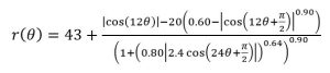 (1)
(1)
where is the angle of a point from the positive x-axis.
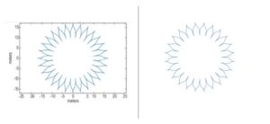
Figure 4: Original shape of starshade for 48 petals from Exo-S report [8] (left). Our attempt at
matching the apodization function on Desmos for 24 petals (right).
Proposed Starshade Model
To experiment and test our inflatable design, a model of our inflatable starshade must be made. Fortunately, due to the shape of the starshade, the optical performance will remain the same when scaled as long as the Fresnel number is the same, and can been seen by the Fresnel diffraction integral for an electric field E0,
![]() (2)
(2)
where r is the radial position, λ is the light wavelength, z is the distance between the starshade to the telescope, ρ is the radial position at the telescope plane, and A(r) is the starshade’s amplitude transmission function [12]. The Fresnel diffraction integral scaled by a factor of s yields,
![]() (3)
(3)
resulting in an unchanged equation, showing that scaling the starshade will not impact its optical performance. With this, we plan to create a 1:100 starshade model built with two mylar sheets cut into the starshade’s shape with an exoskeleton for the gas chambers in between the two sheets. The present state of the model is having the starshade shape cut out of mylar, however, we still need to adhere the mylar sheets and inflate. An exoskeleton is planned to be made with 6mm wide straws glued together, following the layout of the gas channels as seen in Figure 3. The space between the exoskeleton and the sheets of mylar will be glued together by an adhesive suitable for mylar. The straws are not representative of a physical structure for the gas channels, but rather make the pathway of the gas more visible in the model without inflation.
Due to its accessibility and low-cost, mylar was decided as the primary material for the 1:100 model of our rigidizable starshade. Since the full scale starshade is 100 meters in diameter, the model will be one meter in diameter, with the cylinder for the spacecraft bus 0.02 meters in diameter and the central disk was 0.25 meters in diameter. For the model, we need two identical sheets of mylar to create the mask for the model. In order to do this, we created a stencil using a classroom projector, a large piece of poster paper, and the matched function in equation (1). The matched function was projected onto the poster paper, measured, and resized until the function’s dimensions matched those for the 1:100 model. The shape of the function was then traced on the poster paper using a Sharpie marker and cut out along the outside edges. Using painter’s tape to hold down the stencil, we traced the shape twice onto the sheet from the roll of mylar. The two mylar sheets were cut with each having about 1 cm of excess along the edges to account for the space taken up by the exoskeleton, as well as to represent the “paper thin” edges.
Mass Comparison to Required Starshade Design
The mass of our starshade was calculated using the matched function (1). To do this, we needed to find the total surface area of the starshade, as the mass is heavily dependent on how much mylar is used. The total mass of the starshade mask was calculated by integrating the matched function (1) to calculate the total area. The formula to do so is,
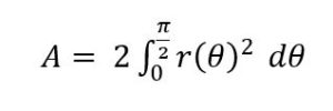 (4)
(4)
Due to the complexity of the integral, Desmos and a Python library, numpy, were both used to calculate the approximate area of the shape [11] [13]. Desmos calculated a total area of approximately 6033 m2 and Python calculated a total area of approximately 6078 m2. The difference in the calculations can result due to the difference in integral calculation method, where Desmos uses a more numeric method, introducing more error. Due to the higher accuracy of numpy, it was determined that it was safest to use the area of 6078 m2 for our mass calculations. To confirm that the calculation was done on the correct regions, the integral (4) was graphed using the Python library, matplotlib.pyplot [14].
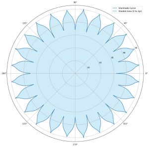
Figure 5: Approximation function graphed using Python library, matplotlib.pyplot.
The blue region indicates the region the area was calculated for.
The calculated surface area of one side of the starshade of 6078 m2 includes the area of the end of the 2-meter-in-diameter cylinder designated for the spacecraft bus in the very center of the starshade and should not be accounted for in the calculation of the total mass [7]. Thus, the area of the spacecraft bus should be subtracted from the total surface area. However, since it is better to have excess rather than a dearth of material, we will continue to use the surface area of 6078 m2 in our upcoming calculations. Since the mask will be used on both sides of the starshade, we double the surface area to 12156 m2.
To calculate the mass, we use the weight of the special mylar used in the Echo 2 balloons, using both the uncoated and coated mylar weights. Both weights are used since NASA plans to coat the starshade with Aluminum, though the coating used on the Echo 2 was Alodine [15]. However, we can still use these weights to predict the potential weight of our starshade since the Alodine coating did not make a difference when reducing the mass [10]. The weight of the uncoated mylar on Echo 2 was 29.9 – 36.5 g/y2 and the weight of the coated mylar was 31.0 – 37.8 g/y2 [10]. Converting to kilograms per meter squared for weight comparison, the weight of the uncoated mylar is 0.036 – 0.044 kg/m2 and the coated mylar is 0.037 – 0.045 kg/m2. Multiplying these weights to the total surface area of our full-scale starshade, we get an uncoated mylar weight of 438 – 535 kg and a coated mylar weight of 450 – 546 kg.
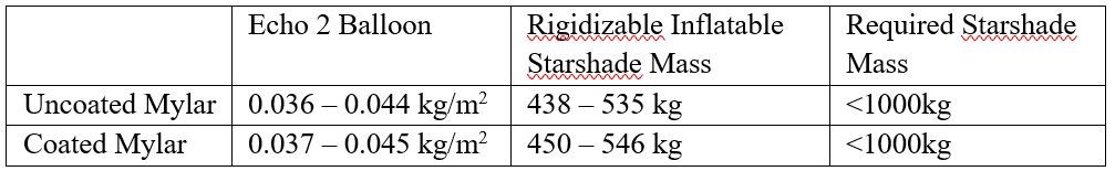
Table 1: Weight comparisons of the starshade designs.
Conclusion
In conclusion, the evolution of the starshade design from its initial concept to the introduction of a rigidizable “skeleton” marks a significant advancement in our research and design. The transition from a purely inflatable design to one that incorporates structural rigidity addresses critical shortcomings identified during testing.
The initial inflatable-only design, while theoretically viable, fell short in maintaining the precise shape and edge sharpness essential for the starshade’s functionality. This deficiency underscored the necessity for a more robust framework, leading to the implementation of the rigidizable skeletal system.
One of the major findings of our research is the substantial reduction in mass achieved with the introduction of the rigidizable skeleton. Uncoated mylar rigidizable inflatable starshade variants exhibit a mass range of 438-535 kg, while coated mylar versions range from 450-546 kg. These figures are significantly lower than the required weight of 1000 kg for the current mission, emphasizing the feasibility and practicality of our proposed design modifications.
Furthermore, the incorporation of the skeletal system has practical benefits beyond shape retention. The division of the central disk and petals into multiple gas chambers significantly increases structural integrity, providing enhanced protection against micrometeoroid impacts and potential gas leakage. Compared to the previous singular gas chamber design, the implementation of multiple chambers reduces the frequency of refills and minimizes gas consumption, thereby optimizing mission efficiency and longevity.
In summary, the refinement of the starshade design through the introduction of a rigidizable inflatable represents a plausible step forward in advancing the capabilities of exoplanet imaging missions. This innovation not only addresses previous design limitations but also reinforces the feasibility and potential of the starshade concept in realizing cost-effective and technologically advanced solutions for exploring distant planetary systems and their tantalizing possibilities for life.
Future Work
For future work, we hope to be able to complete the model and perform more advanced structural analysis of the rigidizable inflatable starshade in order to determine areas of high stress that will require extra sheets of mylar. It is also a possibility to also experiment with different approaches to the “paper thin” edges of the starshade, looking at how the mylar edges affect its optical performance compared to NASA’s original design with optical edges made of chemically etched amorphous metal.
Acknowledgements
We would like to express our sincere appreciation to Dr. Brendan Diamond for his guidance throughout the whole project and Dr. Sean Barton for taking the time to share his expertise in inflatables with us.
Contact: parker.subasic@howardcc.edu, anjolie.tuazon@howardcc.edu
References
[1] NASA, “Exoplanet Program: Starshade Technology Development,” Exoplanet Exploration: Planets Beyond our Solar System, Mar. 16, 2016. https://exoplanets.nasa.gov/exep/technology/starshade/
[2] M. D. Lemonick , “How a Telescope with Sunglasses May Find E.T.,” Time, Feb. 29, 2012. Available: https://content.time.com/time/health/article/0,8599,2107820,00.html
[3] R. Soummer et al., “A starshade for JWST: science goals and optimization,” Proceedings of the Society of Photo-optical Instrumentation Engineers, vol. 7440, no. 0277-786X, Aug. 2009, Accessed: Feb. 24, 2024. [Online]. Available: https://dspace.mit.edu/handle/1721.1/58567
[4] S. Seager, “Exoplanet Space Missions,” Sara Seager. https://www.saraseager.com/exoplanet-space-missions (accessed Feb. 24, 2024).
[5] J. W. Arenberg, A. D. Harness, and R. M. Jensen-Clem, “Special Section on Starshades: Overview and a Dialogue,” SPIE Digital Library, Jun. 21, 2021. https://www.spiedigitallibrary.org/journals/Journal-of-Astronomical-Telescopes-Instruments-and-Systems/volume-7/issue-02/021201/Special-Section-on-Starshades-Overview-and-Dialogue/10.1117/1.JATIS.7.2.021201.full?SSO=1&tab=ArticleLinkFigureTable#_=_ (accessed Feb. 23, 2024).
[6] NASA, “Habitable Exoplanet Observatory (HabEx),” Nasa.gov, 2019. https://www.jpl.nasa.gov/habex/
[7] AIP, “StarShade Undergraduate Challenge: Structural Design Fall 2023 | American Institute of Physics,” www.aip.org. https://www.aip.org/starshade
[8] NASA, “Exoplanet Program: Starshade Technology Development,” Exoplanet Exploration: Planets Beyond our Solar System, Oct. 23, 2023. https://exoplanets.nasa.gov/exep/technology/starshade/
[9] Britannica, “Echo | satellite,” Encyclopedia Britannica, Aug. 07, 2019. https://www.britannica.com/topic/Echo-satellite
[10] NASA, “NASA – NSSDCA – Spacecraft – Details,” nssdc.gsfc.nasa.gov, Oct. 28, 2022. https://nssdc.gsfc.nasa.gov/nmc/spacecraft/display.action?id=1964-004A (accessed Feb. 24, 2024).
[11] Desmos, “Desmos Graphing Calculator,” Desmos Graphing Calculator, 2024. https://www.desmos.com/calculator
[12] P. Willems, “NASA – Starshade to TRL5 (S5) Technology Development Plan,” nssdc.gsfc.nasa.gov, Dec. 6, 2018. https://exoplanets.nasa.gov/internal_resources/1033 (accessed Feb. 23, 2024).
[13] Numpy, “NumPy,” Numpy.org, 2009. https://numpy.org/
[14] MatPlotLib, “matplotlib.pyplot — Matplotlib 3.5.2 documentation,” matplotlib.org, 2024. https://matplotlib.org/stable/api/pyplot_summary.html
[15] A. Harness et al., “Starshade Technology Development Activity Milestone 2: Optical Model Validation,” 2022. Accessed: Feb. 24, 2024. [Online]. Available: https://exoplanets.nasa.gov/internal_resources/2526/