
|
Can Posterior AFOs Be 3D Printed Using Reinforced Composites with Optimized Mechanical Performance and Lower Cost Compared to Traditional AFOs? Meklit Yante, Howard Community College Mentored by: Mark Edelen, M.S. |
Abstract
This research focused on creating a posterior ankle foot orthotic (AFO), addressing two main issues: the expense of functional AFOs often not covered by insurance and the ineffectiveness of cheaper online alternatives. AFOs provide lower extremity support, and this study utilized 3D printing with continuous carbon fiber reinforcement to develop a cost-effective, mechanically equivalent AFO compared to high-cost commercial options. A carbon-fiber reinforced nylon AFO was designed, 3D printed and tested using a custom apparatus to compare flexion stiffness against a purchased carbon fiber AFO and a purchased polyethylene AFO. Results showed that plantarflexion stiffness for the 3D-printed AFO (0.799 Nm/degree) was higher than the carbon fiber AFO (0.643 Nm/degree) and much higher than the polyethylene AFO (0.285 Nm/degree). For dorsiflexion stiffness, the 3D-printed AFO measured 0.204 Nm/degree, the carbon fiber AFO was 0.628 Nm/degree, and the polyethylene AFO was 0.143 Nm/degree. Cost analysis revealed that the 3D-printed AFO was substantially cheaper at $30.79, compared to $509.99 for the carbon fiber AFO and $44.50 for the polyethylene AFO. Weight analysis showed the 3D-printed AFO weighed 1.05 N, while the carbon fiber AFO and polyethylene AFO weighed 1.89 N and 0.891 N respectively. Therefore, the research demonstrates that a 3D printed AFO made using continuous carbon fiber reinforcement has stiffness comparable to traditional carbon fiber AFOs at much lower cost, providing a viable solution for patients.
Introduction
Ankle-foot orthoses are used by people with physical impairments and foot deformities such as foot drop, a condition characterized by the inability to properly lift the front end of the foot [1]. AFOs are often prescribed for individuals with nerve damage, muscle weakness, or alignment issues affecting the lower limb. They help support ankle alignment, improve walking mechanics, and prevent falls by maintaining proper foot positioning during gait [2]. Foot orthoses come in different variations ranging from standard ready-made to custom-fitted braces. Many users of AFOs experience issues such as improper fit and discomfort. With the natural need of the foot to adapt to any uneven terrain, it can become difficult to create a proper design that can mimic the foot’s absorption of shock and support of the entire body’s weight. Recent investigations into carbon fiber-reinforced nylon filaments have demonstrated that additive manufacturing can produce high-performance components with enhanced mechanical properties and design flexibility [3]. As a result, orthoses have evolved to incorporate more advanced geometries and material combinations, improving patient-specific functionality while lowering production time and cost. In clinical practices, many AFOs use materials such as thermoplastics, UD-flex, and carbon fiber, which tend to be less expensive compared to newer types of AFOs such as AF Servo and TurboMed [4]. In this experiment, an AFO was 3D printed and compared to two purchased AFOs. Using a Markforged X7 industrial printer gave researchers an advantage of creating more optimized designs with newer technologies involved in 3D printing AFOs. The X7 utilizes continuous carbon fiber reinforcement to print parts that have high stiffness-to-weight ratio and sufficient dimensional precision for orthotics [5]. For this research, the AFO was printed using Onyx, a Markforged filament consisting of nylon embedded with chopped carbon fiber; this served as the matrix material through which continuous carbon fiber is deposited in a certain number of layers.
In the human leg, there are two types of movements that take place when a person is walking, dorsiflexion and plantarflexion. Dorsiflexion represents the motion where the forefront of the foot moves upward, and plantarflexion represents the downward motion of the forefront of the foot [6]. For this project, the plantarflexion stiffness, the dorsiflexion stiffness, the cost and the weight of the two commercial off-the-shelf AFOs, one made from carbon fiber and the other from polyethylene, were compared to that of the 3D printed AFO. In order to carry out the experiment, a physical test was conducted in two directions to find the stiffness of each AFO. Previous research experiments conducted to test the strength of 3D printed prosthetic sockets and 3D printed prosthetic feet were reviewed and used as inspiration to design the test rig displayed [7]. Ideas such as position of the material to be tested, the direction to test the plantar stiffness and dorsal stiffness as well as the orientation through which force should be applied were used to set up the experimental design for this research. Based on those inspirations, a custom designed apparatus was prepared and the 3D printed leg wearing the AFO was loaded. The test was done in both a dorsiflexion position and plantarflexion position in separate experiments [8]. Additional information was gathered from research done on the evaluation of experimental setup that was used to test the stiffness of AFOs [9]. This article provided a good starting point in constructing a semi-automated experimental setup [10]. Once the test rig was put in place, the artificial leg wearing the AFO was loaded, then the PASCO Material Testing Machine sensed and recorded simultaneously by using a computer software and semi-automated testing aid. As Hochmann (2020) discusses, although mechanical testing provides important insights, it cannot fully replicate the long-term performance of AFOs under real-world usage conditions [11]. Although not a focus of this study, this would be an important and interesting area for future research. In addition to that, future studies will be needed to get a better understanding of how these tests can relate to an AFO’s full capabilities. This will include the common uses of an AFO and how they can be applied to helping people with physical disabilities, which include treating a variety of musculoskeletal and neurological disorders. This AFO is designed to naturally mimic the foot and leg’s movement, helping to maintain proper alignment and providing user with comfort and support while walking. This study aims to use continuous carbon fiber reinforcement to 3D print a posterior AFO with comparable stiffness and lower cost compared to that of a traditional AFO.
Methodology
2.1 Purchasing & Manufacturing of 3D printed AFOs
Three different AFOs were compared based on their strength, stiffness, weight, and cost. Two were purchased and the third one was 3D printed using a Markforged X7 3D printer, which allowed the use of continuous carbon fiber reinforcement to print parts with dimensional accuracy and a high stiffness-to-weight ratio. The goal was to make an AFO that is comparable with the expensive, stiff purchased AFO, but for the cost of the cheaper, low-stiffness AFO. The first brace was manufactured by a company called AliMed, the model was 63497 Swedish AFO. It was made from polyethylene material, and it was purchased for $44.50, see figure 1 on the left. The second brace was manufactured by a company called Brace Direct; the model was Elite Spiral AFO L1951. It was made from carbon fiber and cost $509.99, see (Figure 1) on the right. The third brace was designed using CAD software which went under seven different versions, before reaching a final optimized version, see (Figure 2) for the CAD model AFO and figure 4 for the printed AFO. The production cost was $30.79, and the material used was Onyx, a combination of nylon and carbon fiber. All three AFOs were right leg and sized to fit women’s US size 6.
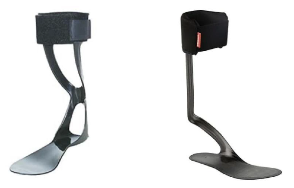
Figure 1: Purchased Braces; Polyethylene Brace (Left) and Carbon fiber Brace (Right)
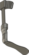
Figure 2: CAD model of the 3D printed AFO
With this design, the AFO was then 3D printed under the Markforged X7 which took 21 and a half hours. The design needed to be printed with separate parts due to several reasons. The main reason being that printing the separate parts allows the optimization of stiffness in specific directions and prevents the weak z-axis. In addition to that, printing the parts separately reduces the cost by minimizing the amount of support material, which allows for customization of stiffness by altering the number of layers incorporated, where increased number of layers yield higher stiffness and vice versa. Lastly, it makes it easier to repair because just the broken part can be replaced instead of the whole AFO. Therefore, the three parts were printed separately and were assembled to yield the AFO displayed in (Figure 4).
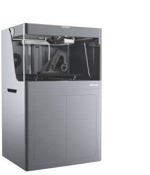
Figure 3: Markforged X7 3D printer used to print the AFO and the artificial leg
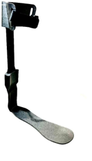
Figure 4: Photograph of 3D printed AFO, composed of three parts; the leg attachment, the adjustable rod, and the foot support.
2.2 Continuous carbon fiber reinforced AFO design
Carbon fiber reinforcement filaments were layered throughout the middle of the AFO with 32 layers. This layout is demonstrated in (Figure 5) where the blue lines represent the layout of the continuous carbon fiber reinforcement. The MarkForged X7 can print with multiple materials. Nylon reinforced with carbon fiber was the material used for this brace. To accurately assess its stiffness and performance under applied force, a detailed model was created to examine these factors and other functional characteristics.
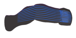
Figure 5: CAD model of the interior of the printed AFO displaying the layers of the carbon fiber
2.3 Experimental setup of the artificial leg wearing the AFO loaded into the testing apparatus
In order to obtain numerical data for the experiment, the setup shown on figure 6 was created and the testing apparatus shown on figure 7 and was used to collect data. The PASCO ME-8236 material testing apparatus was used as part of the test rig. Using computer software connected to the physical machine, data was collected simultaneously while running the experiment. The PASCO apparatus applied force using a push pin force mechanism while winding it down manually with a crank. When the roller bearing touched the surface, a graph was generated on a computer screen through a software called Capstone as displayed on figure 8. This recorded the force applied to the brace, as well as the displacement of that brace as the result of the applied force.
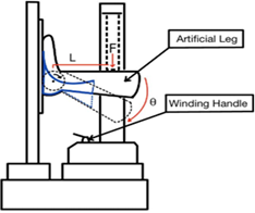
Figure 6: Diagram of test apparatus, showing the movement path (dotted lines) as F force is applied. The angle created (𝚹) and the distance (L) from the pivot point to the force application are labeled. Red markings indicate key variables, while blue markings show the brace’s location.
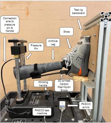
Figure 7: Testing Apparatus
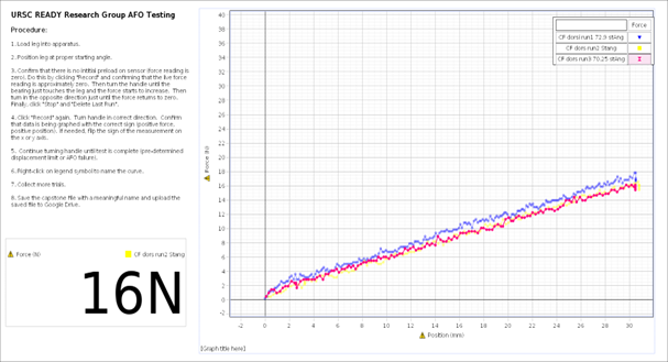
Figure 8: Example raw data (force vs position) collected through Capstone
The test rig design involved a modified apparatus that kept the artificial leg in place. A shoe was purchased and placed on the foot of the artificial leg to give a more realistic test and to support by using the friction of the bottom of the shoe to secure it in place. The design of the apparatus supported both plantarflexion and dorsiflexion position. As the person conducting the experiment applied force downward using the manual hand crank, the testing apparatus began to lower down to the inside crevice of the leg. The angle of the leg was taken at the beginning of each test for the conversion to torque vs. angle to obtain proper stiffness analysis. Once the roller bearing touched the leg, the force and displacement mentioned above were collected. After that, the raw data for force was converted to torque using the formula displayed next to equation 1 and the displacement was converted to angle using the formula displayed next to equation 2.
 2.4 Manufacturing and analysis of 3D printed model leg
A leg design was made to mimic the structure of a young adult female. This gave the braces something to attach to and simulated how the leg would move, and resist force exerted by the weight of the person wearing it. Using the MarkForged X7 3D printer, the artificial leg displayed on figure 9 was printed. This artificial leg resembled the anatomy of that of a typical human leg, thus it was compatible with the three AFOs tested.
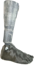
Figure 9: 3D printed artificial leg used for testing
Results
The study conducted tests to evaluate the mechanical properties and cost-effectiveness of the 3D printed AFO compared to traditional options. Through rigorous experimentation and analysis, it was found that the 3D printed AFO made from nylon with continuous carbon fiber reinforcement exhibited impressive plantarflexion stiffness, measuring at 0.7985 Nm/degree.
This result was particularly significant as it closely matched the stiffness of the purchased carbon fiber AFO which was 0.6429 Nm/degree- renowned for its high stiffness and effectiveness in providing support for patients with foot drop. Conversely, the purchased polyethylene AFO, while more affordable, demonstrated significantly lower plantarflexion stiffness value of 0.2847 Nm/degree, indicating potential limitations in providing adequate support for individuals with foot drop. Compared to plantarflexion, the dorsiflexion stiffness recorded was lower, measured at 0.2039 Nm/degree for the 3D printed AFO made from nylon with continuous carbon fiber reinforcement, 0.6429 Nm/degree for the purchased carbon fiber AFO and 0.2847 Nm/degree for the polyethylene AFO. Since foot drop primarily affects the ability to lift the foot during the swing phase, some reduction in dorsiflexion stiffness may actually support smoother toe clearance and a more natural gait. As long as plantarflexion is adequately controlled for stability, lower dorsiflexion stiffness may not significantly hinder overall AFO performance, offering flexibility in design without compromising functional support. However, further research will be required to better support this observation and fully understand its clinical implications. In addition to mechanical performance, the study also examined the cost-effectiveness of the different AFO options. The 3D printed AFO emerged as a highly cost-effective solution, with a production cost of only $30.79. This cost was much lower than the purchased carbon fiber AFO, priced at $509.99 while remaining competitive with the polyethylene AFO, which cost $44.50.
The results showed that the printed carbon fiber AFO weighed 1.05 N, while the purchased carbon fiber AFO weighed 1.89 N, and the purchased polyethylene AFO weighed 0.891 N. Overall, the findings of this experiment are substantial, as they demonstrate the potential for advanced manufacturing techniques like 3D printing to significantly reduce the financial burden associated with acquiring essential medical devices such as AFOs.
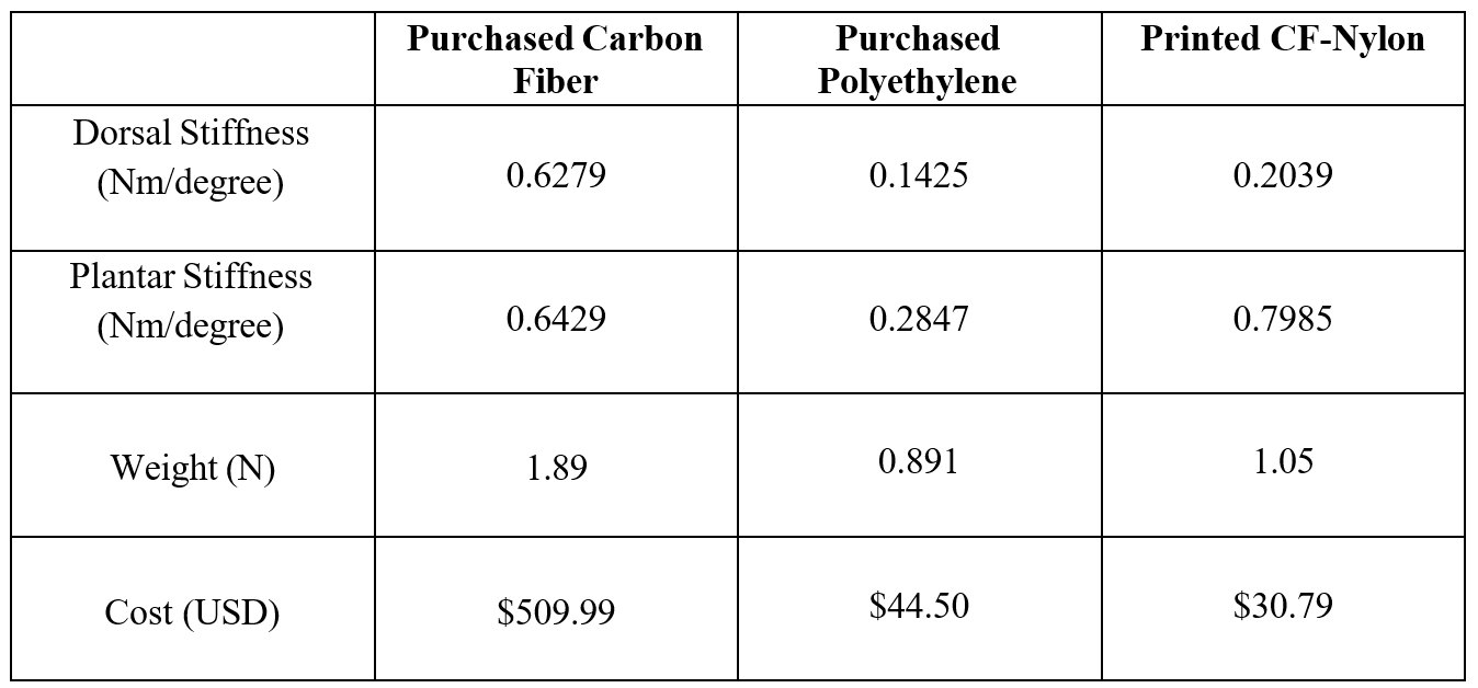
Table 1: Summary data table for all three braces that were tested. The cost for each brace reflects the purchase value for the first two AFOs and the material costs for the third AFO
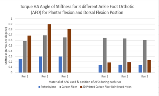
Figure 10: Stiffness comparison, including all trials
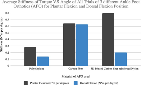
Figure 11: Average stiffness comparison
Discussion
The stiffness of an AFO is of paramount importance in effectively managing foot drop and providing stability during walking. Proper stiffness ensures that the AFO can resist deformations under load and maintain the desired foot alignment throughout the gait cycle. For patients with foot drop, achieving the optimal balance of stiffness is crucial, as excessively stiff AFOs may restrict natural foot movement and lead to discomfort or skin irritation, while inadequately stiff AFOs may fail to provide sufficient support, compromising mobility and safety; the data from this study highlights the functional significance of stiffness in AFOs.
Although there is not a universal optimal stiffness range for all AFO users, factors such as patient’s gender, anatomy of their leg, weight, activity level, and gait abnormalities must be considered in determining the appropriate stiffness level for each individual and the unique design of the 3D printed AFO makes it possible to tailor the brace to achieve different stiffnesses by changing the number of carbon fiber layers. When compared to the traditional carbon fiber AFO, the stiffness proved to be higher in the planar flexion stiffness and lower in the dorsal flexion stiffness. Considering that the 3D printed AFO is made for patients with foot drop whose plantarflexion is very strong and their dorsal flexion is weak, they require a brace with strong planar stiffness that supports the pressure applied by their foot and light dorsal stiffness to maintain balance between the upward and downward position of the foot. Therefore, the 3D printed AFO with continuous carbon fiber reinforcement demonstrated its potential to provide effective support for patients with footdrop while offering a more affordable alternative.
Conclusion
In conclusion, the findings of this research support the feasibility and effectiveness of utilizing 3D printing and continuous carbon fiber reinforcement to produce cost-effective AFOs with comparable stiffness to traditional options. By addressing both the mechanical and financial aspects of AFO design, this approach has the potential to significantly improve access to essential assistive devices for patients with footdrop, ultimately enhancing their mobility and quality of life. However, it’s important to acknowledge the limitations of the study and identify areas for future research. Specifically, additional investigations are needed to explore factors such as comfort, which was not addressed in this study since this experiment was conducted on a 3D printed foot. Understanding these factors would provide a more comprehensive assessment of AFO capabilities and limitations, ensuring optimal design and functionality for individual patient needs. Additionally, future studies could explore how the number of layers in 3D printed AFOs can be modified to achieve a desired stiffness. Another future study that could be of interest involves integrating smart technology into the 3D printed AFOs to send walking reminders to the user, track steps, and report to healthcare providers. This advancement could be valuable in helping patients reduce their long-term dependence on AFOs as it could encourage consistent movement and support recovery. While it may not benefit individuals with complete nerve damage, it holds significant potential for those with muscle weakness or alignment issues. Over time, the stiffness can be gradually decreased as the patient gains strength and/or stability, potentially reaching a point where minimal support or no AFO at all is required. While the integration of technology may result in a slight increase in the cost of the AFOs, the added functionality would offer significant value to the user.
Acknowledgements
We would like to express our sincere gratitude to the Engineering Lab at Howard Community College (HCC) for providing the resources essential to our research. We are especially thankful to the faculty of the Undergraduate Research and Science Curriculum (URSC) program for their continued guidance and support. The well-structured, two-year curriculum has been instrumental in shaping our research journey. We also gratefully acknowledge the program’s generous funding, which made this project possible.
Contact: medelen@gmail.com, meklityante@gmail.com, willdiguiseppe1@yahoo.com, gracenallen@gmail.com
References
[1] E. Wojciechowski et al., “Feasibility of designing, manufacturing and delivering 3D printed ankle-foot orthoses: A systematic review,” Journal of Foot and Ankle Research, vol. 12, no. 1, Jan. 2019, doi: 10.1186/s13047-019-0321-6.
[2] C. Hunter, “Foot orthotics assessment,” Physiopedia, [Online]. Available: http://www.physio-pedia.com/Foot_Orthotics_Assessment. [Accessed: 20-Mar-2023].
[3] F. Calignano, F. Lavecchia, G. Maizza, and M. Manfredi, “Investigation of the mechanical properties of a carbon fibre-reinforced nylon filament for 3D printing,” Machines, vol. 8, no. 4, pp. 74:6-9, Dec. 2020, doi: 10.3390/machines8040074.
[4] S. Y. Lee, J. S. Jung, and H. J. Shin, “Commonly used types and recent development of ankle-foot orthosis: A narrative review,” Healthcare, vol. 9, no. 6, Art. no. 696, pp. 8, Jun. 2021, doi: 10.3390/healthcare9060696.
[5] Ma and J. M. T. Thompson, “Drivers of mechanical performance variance in 3D-printed fused filament fabrication parts: An Onyx FR case study,” Polymer Composites, vol. 42, no. 10, pp. 5045–5057, Oct. 2021, doi: 10.1002/pc.26145.
[6] Lumen Learning, “Types of body movements,” Lumen Learning, [Online]. Available: https://courses.lumenlearning.com/suny-ap1/chapter/types-of-body-movements/. [Accessed: 27-Dec- 2022].
[7] Kim, J. K. Lee, and H. Park, “3D printed transtibial prosthetic sockets: A systematic review,” Materials, vol. 15, no. 4, Art. no. 1532, pp. 7–8, Feb. 2022, doi: 10.3390/ma15041532.
[8] Stelt and R. Wilke, “Strength testing of low-cost 3D printed transtibial prosthetic socket,” Proceedings of the Institution of Mechanical Engineers, Part H: Journal of Engineering in Medicine, vol. 235, no. 10, Oct. 2021, doi: 10.1177/09544119211031211.
[9] Warder, “Examining the viability of carbon fiber reinforced three-dimensionally printed prosthetic feet created by composite filament fabrication,” International Society for Prosthetics and Orthotics, Conf. Proc., 2018.
[10] Lelapi, G. Di Perri, D. Di Giuseppe, and G. Cappa, “A novel experimental setup for evaluating the stiffness of ankle-foot orthoses,” BMC Research Notes, vol. 11, Art. no. 792, 2018, doi: 10.1186/s13104-018-3904-7.
[11] Hochmann, “Testing procedures for ankle foot orthoses,” Orthopädie Technik, vol. 6, 2020.